 Process
Analysis Toolkit (PAT) 3.5
Help Process
Analysis Toolkit (PAT) 3.5
Help |
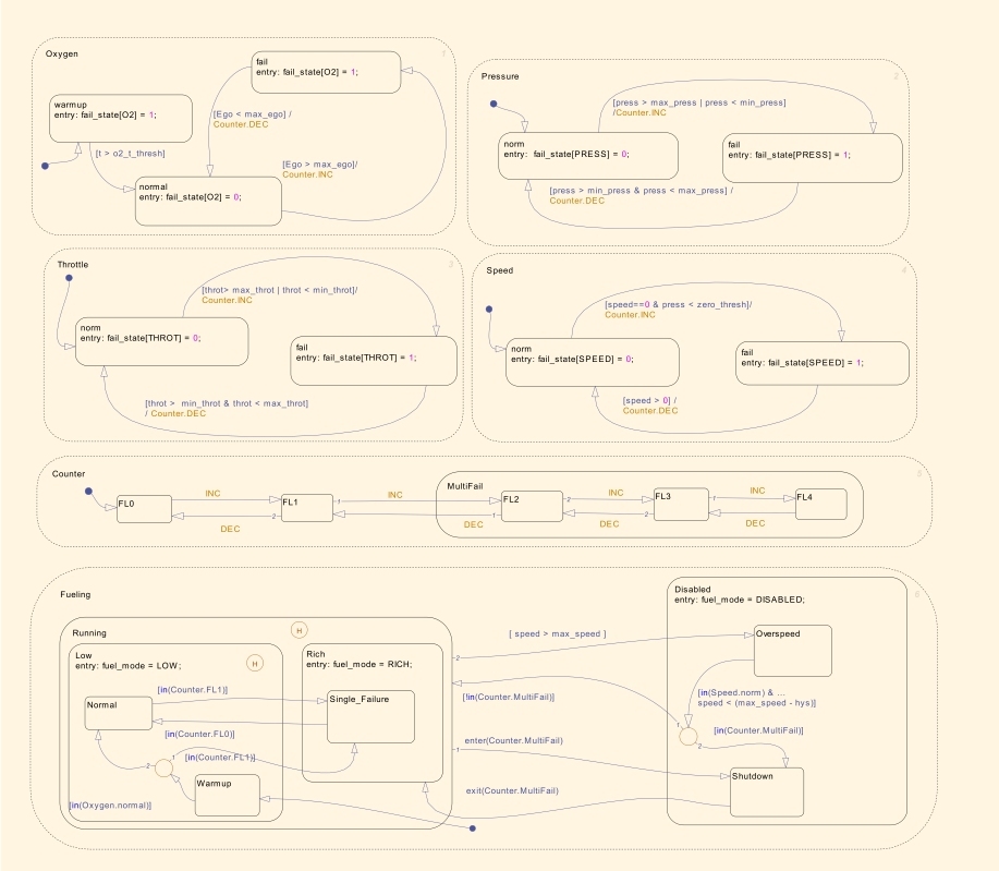
The following Stateflow diagram represents a fault management of a fuel
control system. The diagram contains four parallel states to denote four
separate sensors: a throttle sensor (by state Throttle), a speed sensor
(state Speed), an oxygen sensor (state Oxygen), and a pressure
sensor (state Pressure). Each parallel state contains two substates, a
normal state and a failed state (the exception being the oxygen sensor, which
also contains a warmup state). If any of the sensor readings is outside a predefiend range, then a fault is
recorded (communicated via direct event broadcasting) in the parallel state
Counter, and the corresponding subsystem enters its failed state. If a
subsystem recovers, it can change back to the normal state and the number of
failures decreases accordingly (via direct event broadcasting as well). The parallel state at the bottom of the Stateflow diagram controls the
fueling mode. It regulates the oxygen to fuel mixture ratio. If a failure is
detected, then the oxygen to fuel ratio increases. If multiple failures are
detected, then the fuel system is disabled until there are no longer multiple
failures in the system. Note that history junctions are used in state
Running and state Low respectively to store the last active
fueling mode.
The translated CSP# model is available here. Some improtant Stateflow modeling features, such as History Junctions, Implicit events denoting state entering and exiting, and inter-level transitions, are taken into account.
Copyright © 2007-2012 Semantic Engineering Pte. Ltd.